论文图件绘制任务清单
总体原则
当前论文图件需要服务一条主线:本文不是普通自由空间聚焦,也不是黑箱逆散射重建,而是在多散射体前端优化入射相位,实现散射感知透波聚焦。所有图都应围绕这个判断组织。
图件优先级为:先画概念和方法图,再统一已有数据图,最后补鲁棒性或辅助任务图。图中尽量使用英文标注,方便后续直接转 TAP 英文稿。
当前临时占位图
先将 AI 生成的 Figure 1/2 合成概念图放入总稿,作为展示和叙事判断用的临时版本:
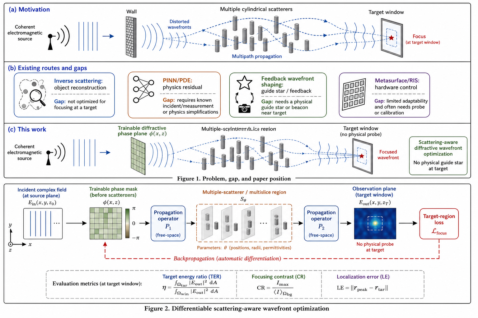
后续如果要投稿,需要把这张图重画成可编辑矢量图,统一字体、线宽、英文标注和版式。
Figure 1: Problem, Gap, and Paper Position
用途:第一张图回答“这篇论文到底解决什么问题,和别人有什么不同”。
建议布局:三栏横向。
左栏:应用动机。画一个发射端、墙体或多散射体、目标区域。标注 through-obstruction sensing / transmission focusing / multiple scatterers。这里不要画成真实穿墙雷达完整系统,避免论文被绑定到 TWRI 成像。
中栏:已有路线和缺口。用四个小块表示 inverse scattering reconstruction、PINN/PDE solving、wavefront shaping with feedback、programmable metasurface control。每个小块下方写一句限制:reconstructs object, not phase design;requires PDE solving;requires guide star/feedback;hardware-centric。
右栏:本文路线。画 trainable diffractive phase before scatterers,经过 scatterers 后在 target window 聚焦。标注 differentiable scattering-aware phase optimization, no physical guide star at target。
画图提示词:
Draw an IEEE journal style conceptual figure with three horizontal panels on a white background. Panel (a) shows an electromagnetic wave passing through multiple cylindrical scatterers toward a target region, motivated by through-obstruction sensing and transmission focusing. Panel (b) compares existing routes using four compact blocks: inverse scattering reconstruction, physics-informed PDE solving, feedback-based wavefront shaping, and programmable metasurface control; each block has a small icon and a short limitation. Panel (c) shows the proposed route: a trainable diffractive phase plane placed before the scatterers, differentiable propagation through multiple scatterers, and a focused energy spot at the observation plane. Use clean vector style, thin black outlines, muted blue/orange/green colors, no decorative gradients, clear arrows, and English labels suitable for IEEE Transactions.Figure 2: Differentiable Scattering-Aware Wavefront Optimization
用途:方法架构图,解释本文怎么优化相位。
建议元素:
- Incident complex field
- Trainable phase mask
- Propagation operator
- Multiple scatterers / multislice scattering region
- Observation plane
- Target-region loss
- Backpropagation arrow to phase mask
需要突出:相位面在散射体前方,目标端没有物理导星或反馈探针。loss 是计算目标,不是实验探针。
画图提示词:
Draw a clean academic architecture diagram for a differentiable scattering-aware wavefront optimization framework. From left to right: incident complex field, trainable phase mask, angular-spectrum propagation, multiple cylindrical scatterers represented as a scattering region, output observation plane, and a target window loss. Add a red dashed backpropagation arrow from the loss back to the trainable phase mask. Label the trainable variable as phase phi(x,z). Add a small note near the target plane: no physical guide star or feedback probe. Use white background, vector style, IEEE paper aesthetics, blue for propagation, orange for trainable phase, gray for scatterers, green for target loss.Figure 3: Competitive Positioning Table / Map
用途:替代简单“本文比球面相位好”的弱叙事,展示本文和方向内代表工作的关系。
推荐形式:二维定位图或紧凑表格。
横轴:research objective,从 object reconstruction 到 wavefront control。
纵轴:information condition,从 data-driven mapping / physics residual / feedback measurement / differentiable forward optimization。
把 DeepNIS、PINN inverse scattering、D2NN、wavefront shaping、metasurface/RIS、neural EM surrogate 和本文放在图上。本文位置应靠近 wavefront control + differentiable forward optimization。
这个图可以先做成 PPT/矢量示意,不一定要直接用 Python 数据图。
Figure 4: Main Focusing and Advanced Baseline Results
用途:主性能图,回答“效果是不是比有竞争力的基线好”。
建议组成:
- Fig. 4a:三圆柱和九圆柱输出面强度图,展示无相位、球面相位、优化相位。
- Fig. 4b:三圆柱和九圆柱目标区能量占比柱状图。
- Fig. 4c:九圆柱高级基线对比柱状图,包含 No phase、Spherical、GS、Proposed,SPGD/TM 可用浅色或附表处理。
已有数据:
chapters/03_transmission_focusing_results_cn.mdadvanced_baselines_results_cn.mdoutputs/advanced_baselines/20260517_200847
注意:TM 当前不能叫 oracle upper bound。
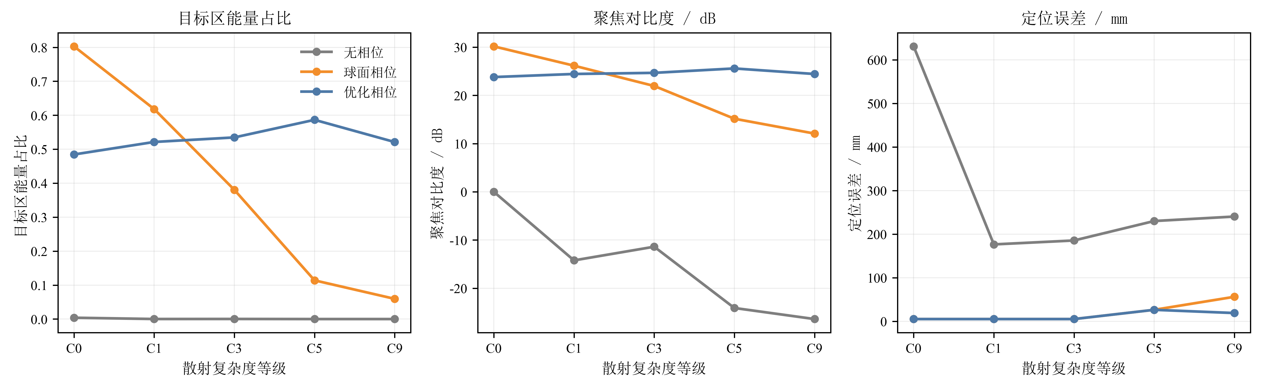
Figure 5: Scattering Complexity Curve
用途:当前最重要的创新证据图。
已有图:
建议最终版本:
- Fig. 5a:target-region energy ratio vs complexity
- Fig. 5b:focusing contrast vs complexity
- Fig. 5c:localization error vs complexity
横轴用 C0、C1、C3、C5、C9。三条曲线为 No phase、Spherical phase、Optimized phase。图注写清楚:lower localization error is better。
需要补充:当前图来自 epochs=60 可视化版,投稿前建议用 epochs=220 或更高复跑。
Figure 6: Target-Position Generalization
用途:回答“是不是只针对一个中心焦点调参”。
已有图:
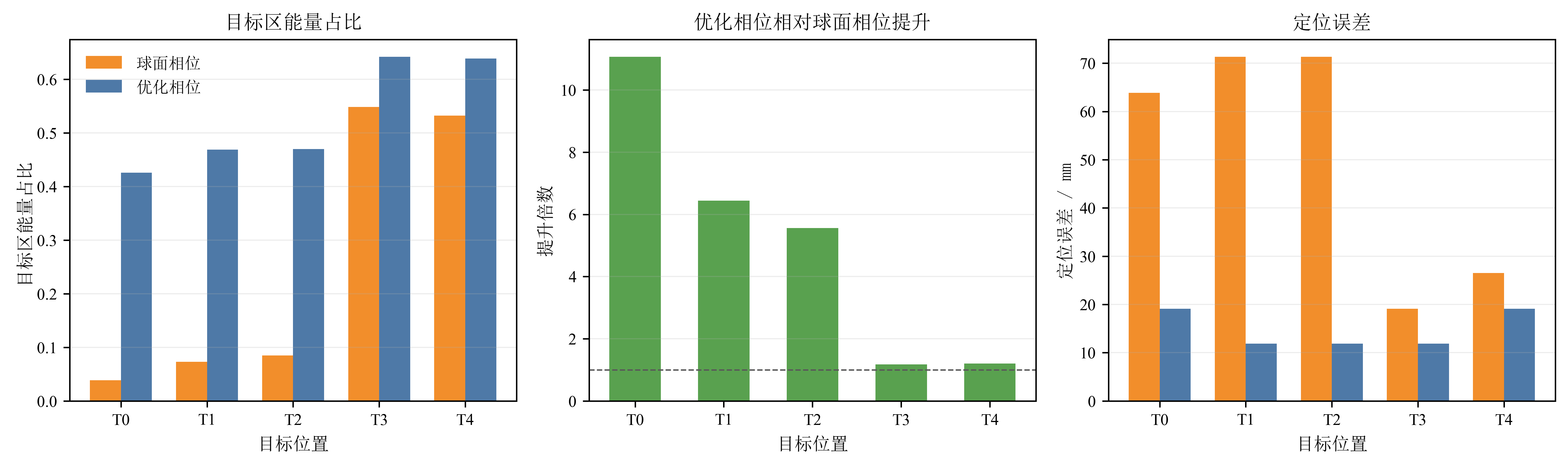
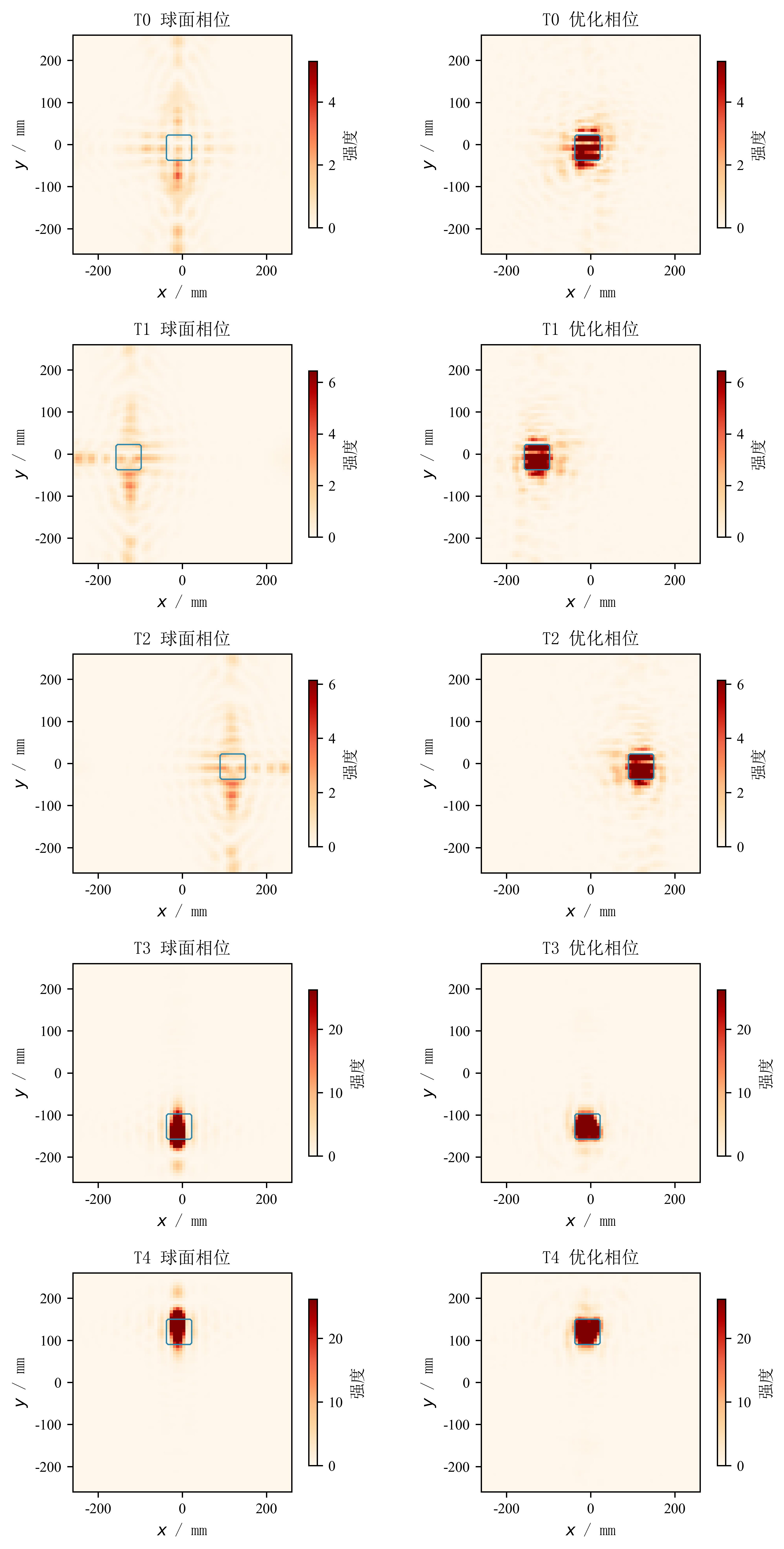
建议最终版本:
- 主文放五个目标点的指标图,显示 optimized / spherical gain。
- 补充材料或汇报放输出面强度矩阵。
- 如果后续扩展到 3×3 目标网格,主文可改成 heatmap。
写图注时必须说明:每个目标位置重新优化相位;不要写成单个相位或单个网络泛化到所有目标。
Figure 7: Learned Phase Interpretation
用途:把性能提升解释成物理上的散射补偿。
已有图:
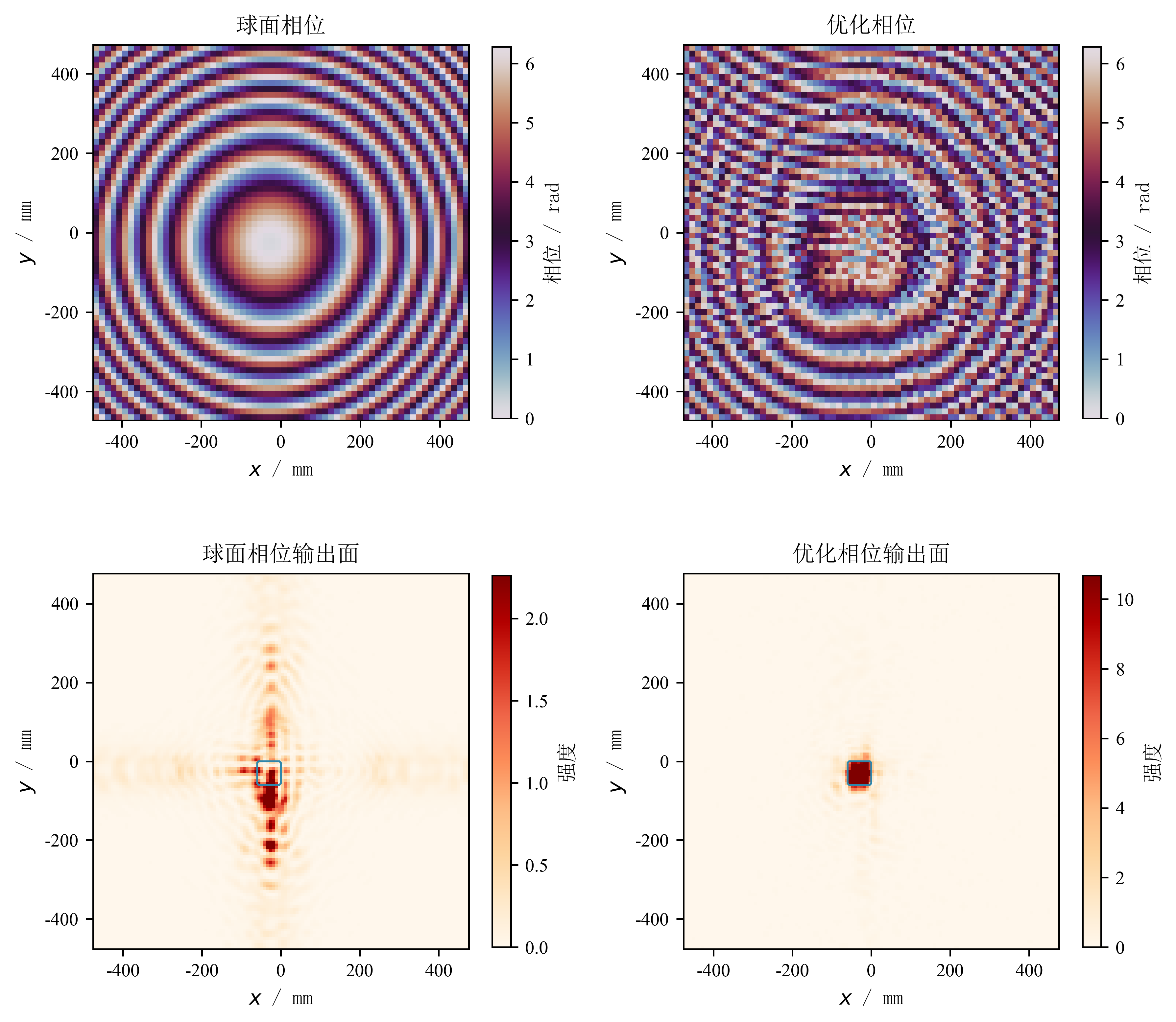
建议补画:
- spherical phase
- optimized phase
- wrapped phase difference
- spherical output intensity
- optimized output intensity
- optional xoz propagation slice
核心图注句:
The optimized phase contains local modulations beyond the smooth free-space spherical phase, indicating compensation associated with the multiple-scattering environment.Figure 8: Robustness or Auxiliary Scattering Control
用途:增强完整度,不建议压过主线。
两个备选:
方案 A:鲁棒性箱线图。做圆柱位置扰动、半径扰动、频率扰动,比较球面相位和优化相位。
方案 B:辅助后向散射抑制。展示同一框架通过替换 loss 可以降低后向散射,但只作为扩展能力,不做主线。
建议优先方案 A。如果来不及补实验,Figure 8 可以暂时不放,避免稿件显得过散。
当前最需要补画的图
优先级 1:重画 Figure 1,弱化 CST,突出本文和 inverse scattering / wavefront shaping / D2NN 的区别。
优先级 2:重画 Figure 2,把方法说清楚,尤其是 phase mask before scatterers 和 loss backpropagation。
优先级 3:统一 Figure 4 到 Figure 7 的配色、字体、坐标轴和图注,使它们看起来像同一篇论文。
优先级 4:如果要最终展示,做一张“story slide”:Problem → Method → Evidence,直接用 Fig. 1、Fig. 2、Fig. 5 的简化版。
文件建议
建议本地新增目录:
tap_paper_package/figures/drawing_sources/用于保存后续手工绘图、PPT 导出、AI 生图提示词和中间版本。Obsidian 只同步最终 PNG,不同步源文件。